

Following our previous article: Anti-SurgeValves for Compressors: Case Studies and Lessons from the Field
Series Overview
Part 1: Anti-Surge Valves for Compressors: Case Studies and Lessons from the Field
Part 2: The Globe vs. Butterfly – The Technical Showdown (You are here)
Part 3: Flow Velocity Control: Restriction Orifices & Piping Layout
Part 4: Flow Direction Selection: Overlooked Critical Details
Part 5: Seat Leakage Classes: Safety & Energy Efficiency Implications
The Globe-Butterfly Dilemma
In current anti-surge applications, MACsystems use both butterfly and globe valves, while BAC systems predominantly use globe valves, with a few butterfly and eccentric rotary valves. In our previous case studies, four out of nine failures involved butterfly valves.Why do butterfly valves fail so frequently? And why do compressor OEMs still specify them?
Two primary reasons:
Cost: Large-diameter globe valves (DN500+) are prohibitively expensive
Lack of awareness: Many engineers don’t fully understand butterfly valve limitations
Let’s examine the fundamental differences.
Valve Characteristics: Two DifferentDesign Philosophies
★Globe Valves: Engineered for Precision
Invented in 1795 and refined during the 1840s steam era, globe valves feature a plug moving perpendicular to the seat. This design provides excellent throttling control and reliable shutoff, making them ideal for modulatingservice and tight isolation. Their inherent characteristic is precision.
★Butterfly Valves: Optimized for Economy
Born in the 1930s and widely adopted after 1960s sealingtechnology breakthroughs, butterfly valves offer low cost, light weight, and compact size for large diameters. Their key attributes are high flowcapacity and low-pressure-drop throttling. However, this comes witha hidden cost: dynamic torque.
The Achilles’ Heel: Dynamic Torque
Butterfly valves are restricted tolow-pressure differential service due to hydrodynamic torque generated during disc rotation. Using a triple-offset butterfly valve as an example (see research: Li Bei, Flow Characteristics & Hydrodynamic Torque Analysis ofTriple-Offset Butterfly Valves, Ningxia University, 2015):
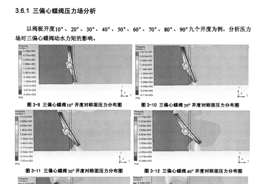
(1) From 10° to 90° opening, thepressure on the upstream disc face is consistently higher than that on the downstream disc face.
(2) From 10° to 80° opening, thepressure on the upper portion of the disc's flow-facing side is greater than that on the lower portion, generating a closing moment. Therefore, during valve opening, the hydrodynamic torque hinders disc rotation, while during closing, it assists the operation. Consequently, the stem torque required for opening exceeds that for closing.
(3) Between 50° and 90° opening, localized high-pressure zones emerge on the upper region of the disc's flow-facing side. As the opening angle increases, the high-pressure area
shrinks while its magnitude intensifies, leading to non-uniform pressure distribution
and unstable opening/closing torque.
(4) From 40° to 90° opening, certainareas on the downstream disc face exhibit pressures lower than those at the inlet/outlet. Notably, between 40° and 60° opening, a continuous low-pressure region forms on the downstream disc surface, amplifying the pressure differential across the disc and resulting in unsteady actuation torque.
Case Study 1 Revisited: 300,000 Nm³/hMAC, DN600Butterfly Valve
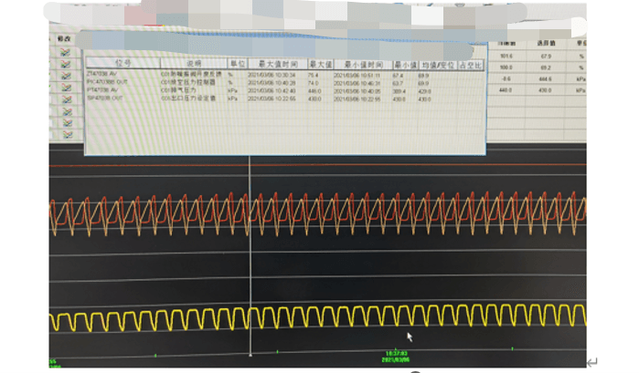
Problem 1: Unstable Valve Position
The DCS trend shows continuous oscillation caused by unstable dynamic torque.
Problem 2: Catastrophic Failure DuringSurge Test
When closing the blow-off valve and increasing pressure:
1,At high pressure, the deviation between command and feedback grew. A 1-2% signal change produced no movement; only at 4-5% did the valve respond.
2,Critical failure: At ~43% opening, the compressor surged. The solenoid de-energized, the control signal increased, but the valve remained stuck. Even disconnecting instrument air pressure didn’t help. Only after manually reducing upstream pressure did the valve snap open.
Why the Valve Fails to Open During Surge
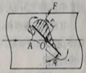
Force Balance Analysis:
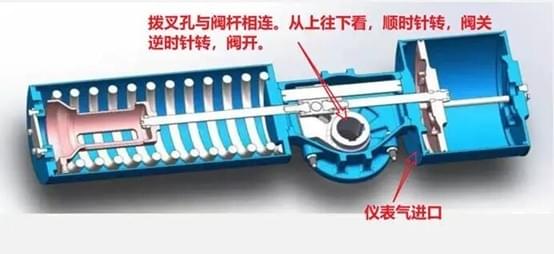
During MAC startup, the anti-surge valvestarts fully open. Instrument air pushes the piston rightward, rotating the fork clockwise via spring force to slowly close the valve and raise discharge pressure.
At any opening, three forces are inequilibrium:
Air Pressure Force (A) + Dynamic Torque (C) = Spring Force (B)
Key Points:
- Dynamic torque (C) always acts in the closing direction
- Torque ÷ Fork Arm Length = Force
The Failure Mechanism:
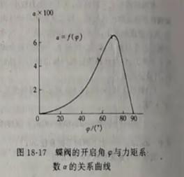
- As the valve closes, C increases (peaking at ~70° opening)
- Spring force B also increases
- When the solenoid de-energizes, A drops to zero
- At the balance point: C = B
- Result: The valve is hydraulically locked—no air pressure remains in the cylinder (the positioner controls position, not cylinder pressure). The valve cannot open during surge.
The Empirical Formula (Use with Caution)
M_max ≈ 0.0654 × D³ × ΔP
D: Diameter (meters)
ΔP: Pressure differential (Pascals)
M_max: Torque (N·m)
The D³ term is brutal for largediameters! For large lines, never use butterflyvalves for anti-surge service.
Large Flow Solutions: The Hybrid Approach
For MAC systems >200,000 Nm³/h, how dowe balance reliability and cost?
Recommended: Globe + Butterfly Combination
- Flow split: 1/3 through globe valve, 2/3 through butterfly valve
- Closing sequence: Close butterfly first, then globe
- Surge response: Open globe valve instantly (typically prevents surge). If full bypass is needed, then open butterfly.
- Normal shutdown: Open globe first to reduce pressure, then open butterfly
Another Risk: Key Connection Failure
During surge (1-second opening requirement), the impact on keyed connections is severe. The photo shows a shearedkey, causing misalignment and seat leakage. Spline connections arestrongly recommended over keyed shafts.

Final Verdict
Primary Choice: Globe valves exclusively
Most reliable, safest, and fastest response.
Alternative: Globe + Butterfly hybrid
Balances cost and reliability for large-flow applications.
Last Resort: Single large butterflyvalve
Lowest cost but highest failure risk—not recommended for critical anti-surgeservice.
Up Next…
Selecting globe valves doesn’t guaranteesuccess. Stay tuned for Part 3, where we’ll dive into:
Flow velocity control and restriction orifice sizing
Piping layout optimization to prevent vibration
- Flow direction selection nuances
- Seat leakage class selection criteria
- Have questions about your anti-surgevalve application? Contact our technical team for a free system review.
This series is based on field data from 20+ air separation units across China. For technical inquiries or case sharing, please reach out to the author.